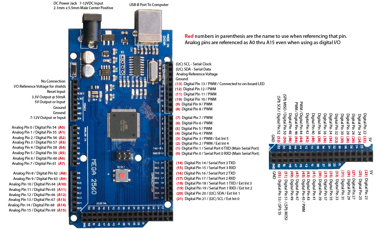
Arduino Mega
- Microcontroller: ATmega2560
- Operating Voltage: 5V
- Input Voltage (recommended): 7-12V
- Input Voltage (limits): 6-20V
- Digital I/O Pins: 54 (of which 15 provide PWM output)
- Analog Input Pins: 16
- DC Current per I/O Pin: 40 mA
- DC Current for 3.3V Pin: 50 mA
- Flash Memory: 256 KB of which 8 KB used by bootloader
- SRAM: 8 KB
- EEPROM: 4 KB
- Clock Speed: 16 MHz
- USB Host Chip: MAX3421E
- Length:101.98mm/4.01in
- Width:53.63mm/2.11in
- Height:15.29mm/0.60in
Original price was: ₹ 1,500.₹ 1,349Current price is: ₹ 1,349.
10% Off
product description
The Arduino Mega is an open-source development board that is developed by the Arduino company. It is based on the Microchip ATmega2560P by Atmel. The Atmega3560P is an 8-bit microcontroller that comes with a built-in bootloader, which makes it very convenient to flash the board with our code. Atmega 2560P based Arduino Mega pinout and specifications are given in detail in the below.The ATmel MCU ATMEGA16U2 MEGA 2560 R3 Improved Version CH340G Board is a micro-controller board base on the ATmega2560. It has a USB host interface to connect with Android based phones, base on the MAX3421e IC.
ATmega2560P has 54 digital input/output pins (of which 15 can be used as PWM outputs); 16 analog inputs, 4 UARTs (hardware serial ports), a 16 MHz crystal oscillator; a USB connection, a power jack, an ICSP header, and a reset button. The MEGA ADK is base on the Mega 2560. Similar to the Mega 2560 and Uno, it features an ATmega8U2 program as a USB-to-serial converter. Revision 3 of the Mega ADK board has a resistor pulling the 8U2 HWB line to ground, making it easier to put into DFU(Device Firmware Upgrade) mode.
Arduino Mega – Basic Features
Arduino Mega – Advanced Features
Digital pins (70):
Digital pins (0-53) + Analog (0-15) = Total Digital I/O pins.
Digital Pins: From 0-53(digital) and 0-15(analog) can be use as input or output for digital transducer and output devices by pinMode() for pin direction, digtalWrite() to write pin and digitalRead() to read pin status.
Analog Pins (16):
Analog pins: From 0-15(analog) can be used as analog input pin for adc, if not used than it work as normal digital pin. It can be used by pinMode() for pin direction, analogRead() to read pin status and get digital value for analog signal, care must be taken for internal or external reference voltage selection and Aref pin.
PWM Pins:
Digital pin 2-13 can be used as PWM output with analogWrite() to write pwm value from 0-255.It’s alternative of DAC for low cost system to get analog signal at output by using filter.
What are the Input and Output Pins of Arduino Mega?
Of the 86 pins available on the Mega board, 72 pins are associated with input and output. In that 54 pins (D0 to D53) are true digital IO pins, which can be configured as per you application using pinMode(), digitalWrite() and digitalRead() functions.
All these Digital IO pins are capable of sourcing or sinking 20mA of current (maximum 40mA is allowed). An additional feature of the Digital IO pins is the availability of internal pull-up resistor (which is not connected by default). The value of the internal pull-up resistor will be in the range of 20KΩ to 50KΩ.
There are also 16 Analog Input Pins (A0 to A15). All the analog input pins provide a 10-bit resolution ADC feature, which can be read using analogRead() function.
An important point about Analog Input pins is that they can be configured as Digital IO pins, if required.
Digital IO pins 2 – 13 and 44 – 46 are capable of producing 8-bit PWM Signals. You can use analogWrite() function for this.


Reviews
There are no reviews yet.